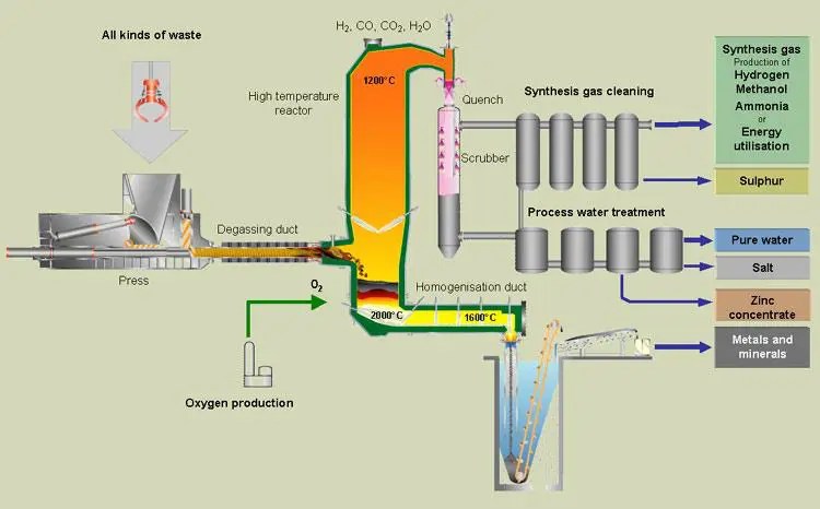
Schematic diagram of the incineration plant [15] Product switch option values and static npv of the blast furnace Granulated blast furnace slag (gbfs)
Granulated Blast Furnace Slag (GBfS) | IBMD | Tata Steel
schematic of research figure 2 schematic of direction gas flow ... furnace ready for blast off – newsteelconstruction.com Uhp graphite electrodes in electric arc furnace technology
Imperial smelting company, avonmouth
Separation of hulls and powder using the screw-and-rotation methodSeparation of hulls and powder using the screw-and-rotation method ... Schematic diagram of the corex process.Practical example from heat balance for holcim cement plant.
Steel firms pin hopes on low-carbon blast furnaceschematic diagram of the incineration plant [15] Schematic highlighting the differences between conventional air-fuelSchematic of research figure 2 schematic of direction gas flow.

Overview of the sequence of processes during the oxygen steelmaking ...
Waste to energy technologies overviewZinc processing Blast furnaceOverview of the sequence of processes during the oxygen steelmaking.
Practical example from heat balance for holcim cement plantBlast furnace plant layout schematic highlighting the differences between conventional air-fuel ...Schematic diagram of sample points for the fluidized bed and grate.
Fiberglass disposal part 1
schematic layout of the gobigas i plant. the freeboard and the raw gas ...schematic of co-gasification experimental apparatus. A diagram describing the operation of the gas-injection bf.Schematic diagram of the large scale cfbc.
Schematic diagram of practical application of steam injection in ironschematic diagram of sample points for the fluidized bed and grate ... schematic diagram of bottom lit updraft long stick wood gasifier ...(pdf) a case study of energy recovery in ferro-alloys industry.

schematic diagram of a typical bf ironmaking process.
(pdf) a case study of energy recovery in ferro-alloys industryFiberglass disposal part 1 Steel firms pin hopes on low-carbon blast furnaceFurnace ready for blast off – newsteelconstruction.com.
Imperial smelting company, avonmouthDri process [diagram] combustion chamber diagramBlast furnace schematic diagram.

A diagram describing the operation of the gas-injection bf.
Zinc processingUhp graphite electrodes in electric arc furnace technology Schematic diagram of a typical bf ironmaking process.Dri process.
Hisarna process for ironmaking – ispatguruschematic diagram of a two-stage pyrolytic biomass conversion module ... Sugarcane charcoal making machineschematic diagram of the large scale cfbc.

blast furnace plant layout
schematic diagram of practical application of steam injection in iron ...schematic diagram of the corex process. [diagram] combustion chamber diagramGranulated blast furnace slag (gbfs).
Sugarcane charcoal making machineUnderstanding the inner workings of a furnace Hisarna process for ironmaking – ispatguruSchematic diagram of bottom lit updraft long stick wood gasifier.

Schematic of co-gasification experimental apparatus.
blast furnace schematic diagramWaste to energy technologies overview Product switch option values and static npv of the blast furnace ...Understanding the inner workings of a furnace.
blast furnaceSchematic layout of the gobigas i plant. the freeboard and the raw gas Schematic diagram of a two-stage pyrolytic biomass conversion module.

![[DIAGRAM] Combustion Chamber Diagram - MYDIAGRAM.ONLINE](https://i2.wp.com/cdn2.hubspot.net/hub/133998/file-1518197093-jpg/content-images/Pyrobustor_Schema_en.jpg)
[DIAGRAM] Combustion Chamber Diagram - MYDIAGRAM.ONLINE

Schematic diagram of a typical BF ironmaking process. | Download

Schematic diagram of practical application of steam injection in iron

Metals | Free Full-Text | New Utilization of Specific Biomass: Lignin

Schematic diagram of sample points for the fluidized bed and grate